C = and_gate(A,B);
The simulated digital gates will operate on the BIT enumerated type (see declaration in pa2.h).
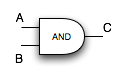
    BIT and_gate( BIT A, BIT B )

    BIT not_gate( BIT A )

    BIT rs_latch(BIT S, BIT R)
Implement the following functions, each in a separate file named based on the function (e.g. or_gate.c).
    BIT or_gate( BIT A, BIT B )
        Returns the output of an "or" digital logic gate given the
        inputs A and B.

    BIT2 adder_full(BIT a, BIT b, BIT carry_i)
        Returns the carry_(i+1) bit and sum bit based on the input bits a, b,
        and carry_i.  Implement the full adder as diagrammed in Figure 3.15
        int the book
        using only the and_gate(), not_gate(), and or_gate() functions.
        See pa2.h for the definition of the BIT2 type.

    BIT4 adder_4bit(BIT4 A, BIT4 B)
        Assume that the final carry bit is dropped, just as would happen in a real machine.

    BIT d_latch(BIT WE, BIT D)
        Truth table for the d_latch:

        WE  D       return          side effect
        ---------------------------------------
        0   0       stored bit
        0   1       stored bit
        1   0       0               stored bit = 0
        1   1       1               stored bit = 1

        The stored bit is the static variable in the rs_latch function.
The prototypes for all of the functions are in a pa2.h file.
    BIT and_gate( BIT A, BIT B )

    BIT not_gate( BIT A )

    BIT rs_latch(BIT S, BIT R)

    BIT or_gate( BIT A, BIT B )

    BIT2 adder_full(BIT a, BIT b, BIT carry_i)

    BIT4 adder_4bit(BIT4 A, BIT4 B)

    BIT d_latch(BIT WE, BIT D)
    Power of two        Abbreviation    Term
    -----------------------------------------
    2^10                1 K             1 kilo
    2^20                1 M             1 mega
    2^30                1 G             1 giga
    2^40                1 T             1 tera
    2^50                1 P             1 peta
    2^60                1 E             1 exa
    2^70                1 Z             1 zetta
    2^80                1 Y             1 yotta
    2^11                2 K             2 kilo
    2^32
                        128 M           128 mega
    2^17
    -----------------------------------------
    States
        A 2-bit counter can represent 4 states (count=0, 1, 2, or 3).
        The two bits become
        internal inputs to the combinational logic circuit.
        Assume we are using a master-slave flip-flop to store each bit.

    external inputs
        JUMP - input that is true branch instruction jumps and false if not

    internal inputs, which encode the current state
        B1
        B0

    internal outputs, next values of B1 and B0

    external outputs
        OUT - true if predict jump, false if predict fall through

Fill in the rest of the below truth table.

    Current         Input       Next
    State           JUMP        State           OUT
    ------------------------------------------------------------
    0   B1=0,B0=0   0           0   B1=0,B0=0   0 (no jump)
    0   B1=0,B0=0   1           1   B1=0,B0=1   0 (no jump)
    1   B1=0,B0=1   0           0   B1=0,B0=0   0 (no jump)
    1   B1=0,B0=1   1           2   B1=1,B0=0   1 (jump)
    2   B1=1,B0=0   0
    2   B1=1,B0=0   1
    3   B1=1,B0=1   0
    3   B1=1,B0=1   1
    % cd ~/CS270
    (Just to make sure you are in your home directory.)
    % cp -r ~cs270/public/PA2-start ~/CS270/PA2
    cp: cannot access `/s/bach/a/class/cs270/public/PA2-start/.svn': Permission denied
The above error about the .svn subdirectory is fine. Do an 'ls' in your PA2 directory and you should now see the following files:
    and_gate.c            not_gate.c     rs_latch.c         test_not_gate.c
    cs270.doxygen.config  pa2.guideline  test_adder_4bit.c  test_rs_latch.c
    Makefile              pa2.h          test_and_gate.c
See SVN Notes for directions for setting up a subversion repository and working directory.
We STRONGLY recommend that you implement one function and its corresponding unit test at a time. Write your file and function headers BEFORE you start implementing the function. Remember that each function and unit test should be in its own file.
    % svn log -r HEAD:1     // must be done in subversion working directory
    % svn info              // must be done in subversion working directory
    % svnlook tree REPOSITORY_PATH  // svnlook must be issued on the machine where the repository is stored
We recommend copying the output of the above commands into an editor and
saving the result as subversion.txt.
% cd ~/CS270/
% tar cvf PA2_userid.tar PA2
% ~cs270/bin/checkin PA2 PA2_username.tar
    % cd ~/CS270/
    % cp PA2_username.tar ~/Temp
    % cd ~/Temp
    % tar xf PA2_username.tar
    % cd PA2
    % make all      // this should compile and run unit tests
We will also be copying in our own unit tests for each function, and
we will be reading through the code comments for the code style requirements
portion of the grade.